10 Grasshopper Plugins Every Computational Designer Should Know

Grasshopper plugins for computational design shown on a parametric model in Rhino

Parametric and computational design have fundamentally changed how architects, engineers and urban designers approach complex geometric problems. Instead of manually constructing every design alternative, computational workflows allow designers to define relationships between parameters, geometry, environmental conditions and performance objectives. Changes to the underlying parameters can then generate corresponding changes throughout a model.

At the centre of many such workflows is Grasshopper, the visual programming environment integrated with Rhinoceros 3D.

According to McNeel’s official Grasshopper documentation, Grasshopper allows users to develop algorithms through interconnected components rather than writing conventional programming code. These definitions can generate geometry, manipulate data, evaluate mathematical relationships and automate repetitive modelling operations.

However, Grasshopper’s significance extends beyond its native capabilities.

A substantial ecosystem of third-party extensions enables users to connect parametric design with environmental simulation, structural analysis, geometric optimisation, mesh modelling, fabrication and information management.

These extensions are commonly called Grasshopper plugins, although some tools have become integrated components of the core software.

The resulting capabilities are especially relevant to contemporary architecture and urban design, where design decisions increasingly involve multiple, sometimes competing requirements.

A facade system may need to balance daylight admission, solar protection, material use and visual character. A lightweight roof may need to respond to geometric constraints while satisfying structural requirements. An urban development proposal may require the comparison of building configurations, solar exposure, circulation and development capacity.

Parametric modelling can make these relationships explicit, but it cannot independently determine which objectives should receive priority.

The distinction between generating geometry, simulating performance and evaluating design alternatives is therefore essential.

A geometrically efficient structure is not automatically structurally safe. An optimised facade may perform well against the numerical objectives selected by its designer while neglecting maintenance, construction complexity or occupant preferences.

Similarly, an optimisation algorithm does not discover an objectively superior architectural solution. It searches for alternatives within the boundaries and evaluation criteria established by the user.

This article examines ten Grasshopper tools with documented relevance to computational architecture and urban design:

  1. Ladybug
  2. Honeybee
  3. Kangaroo2
  4. Karamba3D
  5. Wallacei
  6. Pufferfish
  7. Weaverbird
  8. LunchBox
  9. eleFront
  10. Anemone

The selection covers environmental modelling, physics-based form-finding, structural analysis, evolutionary optimisation, geometric transformation, panelisation, model-data management and iterative computation.

The objective is not to rank the plugins by popularity, but to explain what each tool contributes, how it can be used in a defensible design workflow and where its limitations become important.

Environmental Design and Building Performance: Ladybug and Honeybee

Environmental performance is among the most valuable applications of computational design because geometric decisions affect sunlight access, solar radiation, daylight availability, shading and building-energy demand.

Parametric models allow designers to modify geometry while maintaining relationships with selected environmental variables.

However, environmental modelling requires an important distinction between climate-data visualisation and detailed building-performance simulation.

The Ladybug Tools ecosystem contains complementary applications designed for these different purposes.

1. Ladybug: Climate Analysis and Solar-Responsive Design

Developer: Ladybug Tools community
Official website: https://www.ladybug.tools/ladybug.html
Best for: Climate visualisation, solar studies, shading analysis, sunlight-hours calculations and preliminary environmental design.

Ladybug is an environmental analysis toolkit that connects climate information with parametric geometry.

According to the official Ladybug documentation, the tool imports EnergyPlus Weather files, commonly called EPW files, and produces climate visualisations within Grasshopper.

These datasets can contain information about air temperature, relative humidity, wind conditions, solar radiation and other meteorological variables, depending on the weather file.

Ladybug provides components for producing sun-path diagrams, climate charts, radiation visualisations, sunlight-hours calculations and other environmental outputs.

This makes it useful during the early stages of architecture and urban design, when decisions about building orientation, massing and open-space configuration are still flexible.

How urban designers can use Ladybug

Consider a hypothetical urban design project involving several building blocks arranged around shared courtyards.

The designer may want to understand how variations in block orientation and height affect direct sunlight received by the courtyards.

A Grasshopper definition could parameterise building dimensions, spacing and orientation.

Ladybug could then be used to calculate direct sunlight hours for selected surfaces under defined dates and geographic conditions.

The designer could compare alternative configurations, identify areas receiving more or less direct sunlight and investigate whether changes in massing alter the spatial distribution of solar access.

The same approach can be useful for investigating solar exposure on plazas, pedestrian streets, rooftops and building facades.

Suggested workflow

Begin by constructing or importing the relevant site geometry into Rhino.

Prepare a simplified Grasshopper model in which important parameters such as building height, orientation and spacing can be adjusted.

Obtain an appropriate EPW file for the project location and examine its source and representativeness.

Use Ladybug components to import the climate data and define the analysis period.

Create a suitable analysis mesh for the surfaces being evaluated.

Run the selected solar analysis and compare the resulting values across different design configurations.

For a meaningful comparison, retain consistent weather data, analysis periods and geometric resolution.

Important limitations

Climate simulations are dependent on the quality of the environmental inputs.

A weather file representing a regional airport may not adequately describe microclimatic conditions within a dense urban canyon.

Similarly, solar exposure is only one component of outdoor thermal comfort.

A shaded location is not necessarily comfortable under all weather conditions, particularly where air temperature, humidity, wind and longwave radiation contribute to the thermal environment.

Design conclusions should therefore remain proportionate to the simulated variables.

Ladybug is especially useful for developing climate-responsive design hypotheses, but those hypotheses may require more detailed simulation or field validation.

2. Honeybee: Daylight, Energy and Building-Performance Simulation

Developer: Ladybug Tools community
Official website: https://www.ladybug.tools/honeybee.html
Best for: Daylight analysis, building-energy modelling, thermal performance and environmental simulation.

Honeybee extends the Ladybug Tools ecosystem into more detailed building-performance modelling.

The official Honeybee documentation explains that Honeybee connects Rhino and Grasshopper with established simulation engines, including Radiance for daylight analysis and EnergyPlus/OpenStudio for building-energy modelling.

This enables designers to evaluate aspects of environmental performance that cannot be established through geometry or simple climate visualisation alone.

For example, a facade-design exercise may require more than a calculation of sunlight received on an external surface.

The designer might also need to investigate indoor daylight levels, annual daylight performance, glare risk or the influence of glazing and shading configurations on modelled energy demand.

Honeybee supports such workflows through structured building models and simulation inputs.

How architects can use Honeybee

Consider an educational building whose facade is being developed using a parametric shading system.

The spacing, depth and orientation of the shading elements could be controlled through Grasshopper parameters.

Honeybee could be used to assess alternative configurations using appropriate daylight or energy simulations.

The analysis might reveal that an arrangement reducing incident solar radiation also reduces useful indoor daylight.

The designer would then need to consider trade-offs rather than treating greater shading as universally beneficial.

This illustrates an important advantage of computational performance analysis: it can make the consequences of geometric decisions more explicit.

Suggested workflow

Develop the relevant building geometry and define the rooms or zones required by the selected simulation.

Assign appropriate aperture properties, construction characteristics and boundary conditions.

Prepare the surrounding context, including buildings that may affect shading.

Select the relevant Honeybee workflow for daylight or energy assessment.

Run the simulation using consistent settings across alternatives.

Examine the output values, identify potential performance trade-offs and refine the geometry where justified.

Important limitations

Detailed environmental simulations are sensitive to modelling assumptions.

A building-energy result may depend on occupancy schedules, internal loads, ventilation settings, construction properties and operational assumptions.

Daylight simulation similarly depends on glazing properties, surrounding geometry, sky conditions and sensor placement.

A visually convincing result should not be assumed to represent actual building performance without appropriate validation.

Ladybug and Honeybee should therefore be regarded as complementary rather than competing plugins.

Ladybug is particularly effective for climate understanding and preliminary solar studies, while Honeybee supports more detailed building-performance modelling.

Both are distributed within the wider Ladybug Tools Grasshopper ecosystem, so they are not necessarily independent installation packages.

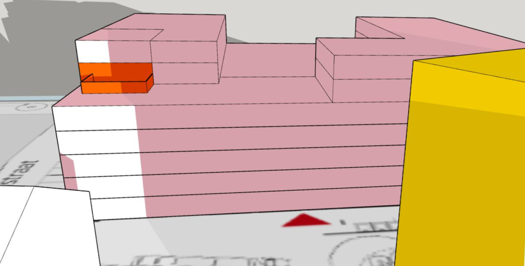
Three-dimensional solar study of a proposed building showing the distribution of sunlight and shadow across its massing
Solar and shadow studies provide a basis for evaluating how building geometry influences sunlight access, although detailed environmental performance requires additional modelling inputs. Image: Invaders~nlwiki, CC BY-SA 4.0, via Wikimedia Commons.

Physics-Based Form-Finding and Structural Design: Kangaroo2 and Karamba3D

Computational geometry becomes particularly valuable when architectural form is influenced by physical behaviour.

Lightweight roofs, tensile membranes, gridshells and structural frames are not simply collections of visually interesting surfaces.

Their geometry interacts with loading conditions, support systems, material properties and construction constraints.

Two Grasshopper tools frequently associated with this field are Kangaroo2 and Karamba3D.

Although both can contribute to structural exploration, they have fundamentally different roles.

Kangaroo2 is primarily a goal-based physics and constraint-solving system, while Karamba3D provides structural finite element analysis.

3. Kangaroo2: Physics-Based Form-Finding and Constraint Solving

Developer: Daniel Piker
Official project: Kangaroo, McNeel Grasshopper community
Best for: Form-finding, geometric relaxation, tensile surfaces, bending-active systems and interactive geometric constraints.

Kangaroo is a physics-based design system developed by Daniel Piker.

Its capabilities include interactive form-finding, geometric relaxation and constraint solving.

An important clarification is that Kangaroo2 is bundled with Grasshopper in current Rhino versions and generally does not require a separate installation.

Daniel Piker confirmed this in the McNeel community documentation, explaining that current Rhino and Grasshopper installations include the relevant Kangaroo version.

Kangaroo2 operates through a system of goals.

These goals can represent relationships such as target lengths, geometric alignment, bending constraints, anchoring conditions and other behaviours.

The solver then seeks a configuration that satisfies or balances the specified goals.

For computational designers, this makes it useful for exploring geometry influenced by constraint relationships.

How architects can use Kangaroo2

Consider the conceptual design of a lightweight canopy over a public gathering space.

A designer could define a network of points and connections representing a simplified structural surface.

Selected boundary points could be fixed, while other points remain free to move.

Appropriate goals could then be applied to investigate a relaxed configuration.

By changing the location of anchors or the relative influence of constraints, the designer could generate different surface configurations.

This process may help identify geometries that are worth investigating through subsequent structural analysis.

Kangaroo2 is also relevant to mesh relaxation, panel alignment and certain deployable or bending-active design explorations.

Suggested workflow

Create a simplified geometric representation of the intended system.

Identify fixed points, boundary conditions and geometric relationships.

Select the relevant Kangaroo goal components.

Connect those goals to the solver and examine the resulting geometry.

Modify parameters such as target lengths, anchoring positions or constraint strengths.

Compare the resulting configurations and assess whether they are appropriate for further design development.

Important limitations

Kangaroo’s geometric equilibrium does not automatically establish structural safety.

A relaxed surface may be geometrically coherent while still being unsuitable for construction because of member strength, buckling, connection design or material behaviour.

The goal-based model may also represent a simplified physical system rather than the actual engineering response of the proposed construction.

Therefore, Kangaroo2 is best used for form-finding and geometric exploration, with structural verification undertaken separately where necessary.

4. Karamba3D: Parametric Structural Analysis

Developer: Karamba3D development team
Official website: https://karamba3d.com/
Best for: Structural analysis, preliminary member sizing, truss and frame studies, shell analysis and structural optimisation.

Karamba3D integrates finite element analysis within the Grasshopper environment.

According to the official Karamba3D website, the platform is intended to support parametric structural analysis during design development.

It allows users to construct analytical structural models and investigate their response under specified loading and support conditions.

For architectural applications, the major advantage is the connection between geometric parameters and structural results.

Rather than modelling a structural configuration once, analysing it separately and manually rebuilding alternatives, designers can establish a workflow in which controlled geometric changes trigger corresponding updates to the analytical model.

How computational designers can use Karamba3D

Consider a pedestrian bridge or a lightweight public-space pavilion.

The designer might create alternative structural configurations by changing the spacing of supports, the depth of structural members or the geometry of the spanning system.

Karamba3D could be used to compare the structural response of these alternatives under defined load cases.

The analysis might identify configurations with different displacement patterns or material demands.

The designer could then examine whether a configuration offering structural advantages also satisfies architectural requirements such as spatial clearance, visual character and construction feasibility.

This is particularly valuable when structural considerations are introduced early rather than postponed until the final form has been selected.

Suggested workflow

Develop the structural geometry within Grasshopper.

Define an analytical model using suitable beam, shell or other supported elements.

Assign material and section properties.

Specify supports, connections and load cases.

Run the finite element analysis.

Examine relevant outputs, such as displacement, internal forces or utilisation indicators, depending on the model and component capabilities.

Revise the geometry or structural properties and compare the results.

Important limitations

Finite element analysis is only as reliable as its assumptions.

Incorrect supports, unrealistic load cases, unsuitable element discretisation or inaccurate material properties can produce misleading results.

A model with apparently low displacement may still require checks for stability, local buckling, connection behaviour, construction sequence and applicable design standards.

Karamba3D is therefore valuable for preliminary structural exploration and informed collaboration between architects and engineers.

It should not be treated as a substitute for a complete code-compliant engineering design process.

The distinction between Kangaroo2 and Karamba3D is essential: one helps explore geometric equilibrium and constraints, while the other provides a framework for evaluating structural response through an engineering model.

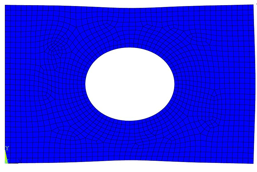
Finite element mesh of a structural domain, illustrating how geometry is divided into discrete analytical elements
Finite element methods divide a continuous structural domain into discrete elements, allowing the response of a defined analytical model to be calculated under specified assumptions. Image: Abhiram vs 24, CC BY-SA 4.0, via Wikimedia Commons.

Evolutionary Optimisation: Wallacei and the Search for Better Design Alternatives

Computational design frequently involves several performance objectives that cannot all be maximised simultaneously.

For example, an architectural facade may need to admit daylight while limiting excessive solar exposure.

An urban massing proposal may seek development capacity while retaining sufficient open space or sunlight access.

These are multi-objective problems because improving one measure can produce an unfavourable change in another.

The challenge is not simply to generate alternatives but to examine the relationships between competing objectives.

5. Wallacei: Multi-Objective Evolutionary Optimisation

Developers: Mohammed Makki, Milad Showkatbakhsh and Yutao Song
Official website: https://www.wallacei.com/home
Best for: Multi-objective optimisation, evolutionary design exploration and comparative analysis of generated solutions.

Wallacei is an evolutionary optimisation engine developed for Grasshopper.

According to its official website and learning resources, the platform combines evolutionary search with analytical tools for examining and selecting design alternatives.

Its documented functionality includes Wallacei X, which supports evolutionary simulations, and Wallacei Analytics, which assists in interpreting the resulting populations.

An evolutionary optimiser explores combinations of design variables and evaluates the resulting alternatives against the objectives supplied by the user.

Over repeated evaluations, it may identify configurations that perform favourably according to those mathematical criteria.

The significance of Wallacei lies in its ability to examine trade-offs across a design space rather than only testing a small number of manually selected alternatives.

How urban designers can use Wallacei

Consider a hypothetical urban block containing several residential buildings.

The designer may wish to investigate three objectives:

  • Increase selected measures of solar access.
  • Maintain a required development capacity.
  • Reduce a defined measure of pedestrian travel distance.

The building locations, heights and orientations could be represented as design variables within a Grasshopper definition.

Environmental and spatial-analysis components could then calculate the relevant performance values.

Wallacei could use these values to search for configurations that perform well under the selected objectives.

The resulting set of solutions may reveal trade-offs between solar access, development capacity and network distance.

However, it is important to distinguish a mathematically favourable solution from a complete urban design proposal.

A configuration performing well against the three selected objectives may still produce poor public-space enclosure, inappropriate building relationships or unacceptable social consequences.

Understanding Pareto-optimal solutions

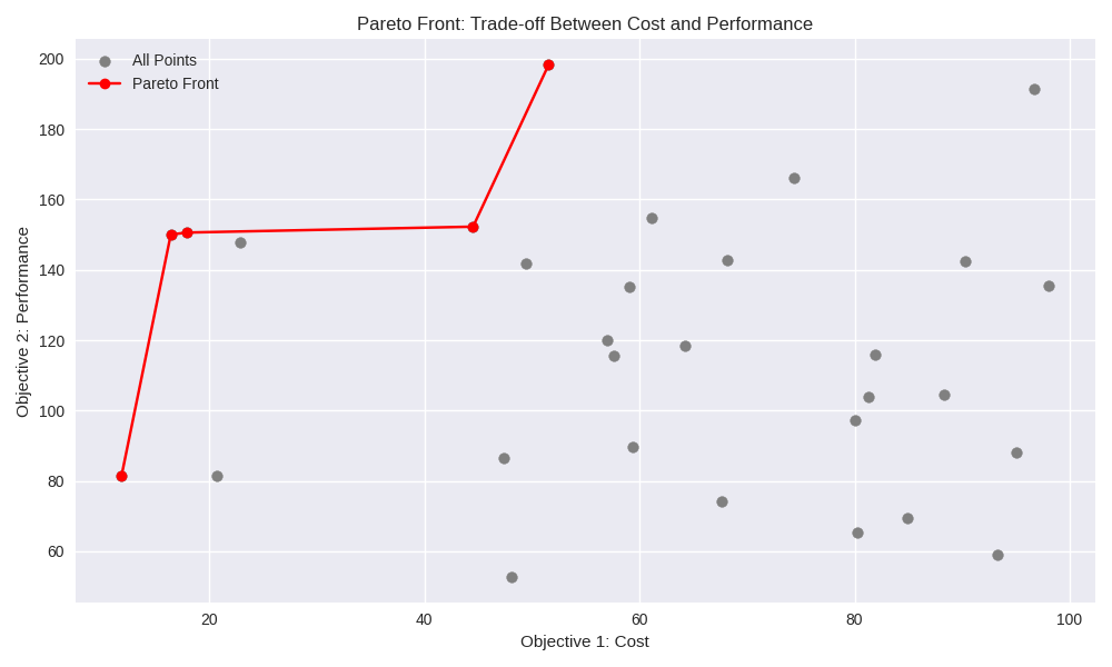
A central concept in multi-objective optimisation is Pareto optimality.

A solution is Pareto-optimal when no other feasible solution improves at least one objective without worsening another, under the stated objectives and comparison rules.

This does not mean the solution is universally optimal.

It means that a defined improvement cannot be obtained without a trade-off within the evaluated set or feasible design space.

A Pareto front can therefore reveal the structure of competing design objectives.

For architectural and urban design research, this may be more informative than presenting a single supposedly optimal scheme.

Suggested workflow

Begin by defining the design problem and the variables that can change.

Establish realistic bounds and geometric or regulatory constraints.

Identify measurable objectives and determine whether each is to be minimised or maximised.

Create Grasshopper components that calculate these objectives for every candidate configuration.

Test the definition with manually selected alternatives before running the evolutionary solver.

Configure Wallacei and undertake the optimisation.

Review the resulting solutions, including their objective values, geometric characteristics and trade-offs.

Select promising alternatives for additional architectural, environmental or engineering evaluation.

Important limitations

Evolutionary optimisation does not guarantee discovery of a global optimum.

Results depend on the algorithm, population size, generation settings, randomness, objective definitions and feasibility constraints.

Computationally expensive simulations can also make large optimisation runs impractical.

More importantly, many architectural qualities are difficult to express as reliable numerical objectives.

Urban identity, social inclusion, experiential quality and cultural significance cannot be assumed to have been optimised simply because the mathematical model has converged.

A rigorous workflow should also test the sensitivity of results to parameter choices and report how the preferred alternative was selected.

Wallacei is consequently most valuable when it supports a transparent comparison of alternatives rather than functioning as an automatic decision-maker.

Diagram illustrating a Pareto front and the trade-off between cost and performance in a multi-objective problem
Multi-objective optimisation can identify sets of competing solutions rather than one universally superior design; the interpretation depends on the objectives and feasible alternatives. Image: Lorepenoten, CC0, via Wikimedia Commons.

Advanced Geometry and Surface Rationalisation: Pufferfish and Weaverbird

Complex architectural geometry often requires more than conventional extrusion, rotation and surface modelling.

Computational designers may need to generate transitions between different shapes, subdivide meshes, create repeating systems or transform irregular surfaces into geometries that can be fabricated.

The following two plugins address related but distinct aspects of this challenge.

Pufferfish focuses on controlled geometric transformation and interpolation, while Weaverbird provides tools for mesh topology, subdivision and transformation.

6. Pufferfish: Morphing, Interpolation and Geometric Transformation

Developer: Michael Pryor
Official community page: Pufferfish, McNeel Grasshopper
Best for: Shape morphing, geometric interpolation, surface transformations and complex form development.

Pufferfish is a collection of Grasshopper components focused on geometric transformations.

Its developer describes its functions as including tweening, blending, morphing, interpolation, averaging and related shape-changing operations.

The Pufferfish component documentation lists tools that allow designers to create and control transitions between curves, surfaces and other geometric systems.

These functions are particularly useful when a design requires a continuous transformation between two or more geometric states.

How architects can use Pufferfish

Consider a pedestrian bridge canopy whose cross-section changes along its length.

The designer may want the canopy to begin with a narrow profile, gradually expand above a public gathering area and then transition into a different geometry near the opposite end.

Instead of manually constructing many intermediate sections, Pufferfish can help create interpolated geometry between defined shapes.

The transformation can be controlled using parameters that influence how the intermediate geometry develops.

Similar workflows may be useful for facade transitions, sculptural installations, roof profiles and architectural envelopes.

In urban design, the approach may also assist with creating formally continuous structures across irregular public spaces.

Suggested workflow

Begin by creating the reference curves or surfaces.

Check their geometric compatibility, including curve direction and control-point organisation where relevant.

Choose a suitable Pufferfish transformation or interpolation component.

Define the transformation parameters and examine the intermediate geometry.

Modify the parameter values to study alternative transitions.

Inspect the resulting surfaces for discontinuities, self-intersections or other geometric problems.

If fabrication is intended, evaluate the geometry using suitable constructability and structural checks.

Important limitations

Geometric continuity does not necessarily indicate structural or manufacturing feasibility.

A smoothly interpolated surface may require complex fabrication or produce irregular panel dimensions.

Morphing can also introduce geometric distortion, particularly when the reference shapes have incompatible parameterisation.

Therefore, Pufferfish is best used for controlled geometric exploration rather than as an automatic method of producing fabrication-ready geometry.

7. Weaverbird: Mesh Subdivision and Topological Transformation

Developer: Giulio Piacentino
Official community page: Weaverbird, McNeel Grasshopper
Best for: Mesh subdivision, smoothing, topological transformation and geometric preparation.

Weaverbird is a mesh-modelling extension developed by Giulio Piacentino.

The official McNeel community documentation describes it as a tool for mesh editing, subdivision and transformation.

Its component set includes methods such as Catmull-Clark subdivision, Loop subdivision, mesh thickening and topological operations.

These capabilities make Weaverbird relevant to architectural surfaces represented through polygonal meshes.

A mesh differs from a smooth NURBS surface because it represents geometry through vertices, edges and faces.

This representation is useful for complex structures, tessellated surfaces and certain fabrication workflows.

How computational designers can use Weaverbird

Consider a curved public-space pavilion represented by a coarse polygonal mesh.

The initial geometry may contain relatively few faces, allowing the designer to develop the overall form efficiently.

Weaverbird could then be used to subdivide or transform the mesh into a denser configuration.

Different subdivision operations may create different geometric and topological outcomes.

The resulting mesh could serve as a basis for further panelisation, visualisation or fabrication-oriented development.

The method is particularly relevant to experiments involving gridshells, faceted architectural envelopes and complex surface patterns.

Suggested workflow

Prepare a clean input mesh and examine its topology.

Check face orientation, boundaries and potential non-manifold conditions.

Apply an appropriate subdivision or transformation operation.

Compare the resulting geometry with the original mesh.

Inspect changes in curvature, edge distribution and polygon density.

Determine whether the output is intended for visualisation, further modelling or fabrication.

If the geometry will be physically constructed, additional structural and geometric rationalisation may be necessary.

Important limitations

Mesh subdivision can increase the number of faces substantially.

A visually smooth result may become computationally demanding and difficult to edit.

Furthermore, smoothing changes the geometry and may alter dimensional relationships, edge locations or clearances.

Not every subdivided mesh is watertight, structurally meaningful or suitable for direct fabrication.

The plugin’s documented development history also spans multiple Rhino generations. Compatibility should be checked before adopting older example files or components in a current workflow.

Pufferfish and Weaverbird should be selected according to the geometric problem.

Pufferfish is particularly useful for controlled transitions between geometric states.

Weaverbird is more directly concerned with the topology and subdivision of mesh geometry.

They can complement one another, but their operations are not interchangeable.

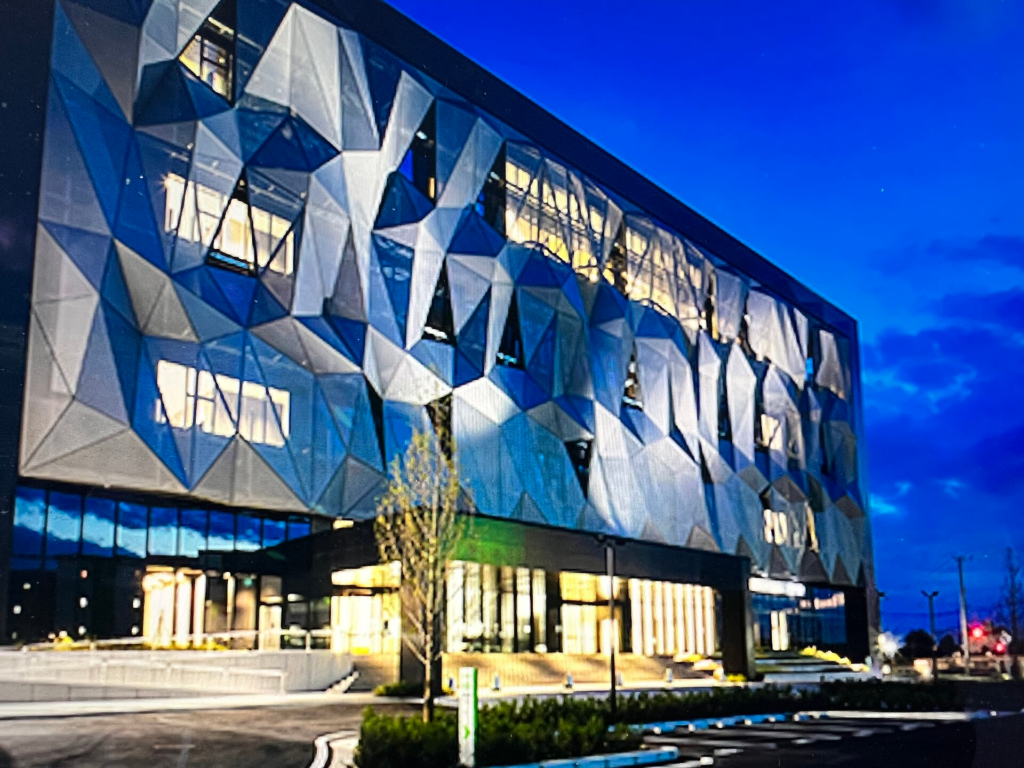
Built parametric facade composed of repeating triangular and polygonal panels across a large building elevation
Complex architectural envelopes demonstrate the importance of geometric subdivision, panel relationships and fabrication constraints in computational design. Image: Tensile facade International, CC BY-SA 4.0, via Wikimedia Commons.

Panelisation, Model Data and Iterative Workflows: LunchBox, eleFront and Anemone

As parametric projects become more complex, the main challenge often shifts from generating geometry to managing the relationships between components.

A computational model may contain hundreds of panels, structural members or repeated objects.

Each object may need an identifier, material classification, dimensions, fabrication information or relationship with other elements.

The designer may also need to run the same operation repeatedly while updating the model after each iteration.

LunchBox, eleFront and Anemone address different aspects of these workflows.

8. LunchBox: Surface Panelisation and Data Operations

Developer: Proving Ground, originally developed by Nathan Miller
Official website: https://apps.provingground.io/lunchbox/
Best for: Panelisation, geometric tessellation, repetitive surface systems and computational data workflows.

LunchBox is a Grasshopper plugin developed within the Proving Ground ecosystem.

According to its official documentation, it provides computational tools for surface tessellation, geometry analysis and data workflows.

It includes components for generating panel patterns and managing geometric operations that occur frequently in computational design.

The official installation documentation confirms that LunchBox can be installed through Rhino’s Package Manager in supported Rhino versions.

For architectural applications, its panelisation functions are especially relevant.

How architects can use LunchBox

Consider a facade composed of repeated triangular panels.

The designer may need to divide a reference surface into a controlled pattern and investigate different panel arrangements.

LunchBox can generate geometric subdivision systems that respond to the underlying surface and selected parameters.

The result may be used to develop facade alternatives, skylight patterns or architectural screens.

In some cases, panel dimensions and orientation may subsequently be evaluated against material or fabrication constraints.

LunchBox also provides data-management tools and machine-learning-related components, as described in its official documentation.

However, these functions should not be interpreted as automatic evidence of design intelligence.

The usefulness of a statistical or machine-learning component depends on the data and analytical question to which it is applied.

Suggested workflow

Construct the reference surface within Rhino or Grasshopper.

Select a panelisation component appropriate to the intended geometric system.

Define relevant parameters such as subdivision counts or pattern characteristics.

Generate and inspect the panel geometry.

Evaluate panel size, shape, orientation and geometric consistency.

If the system is intended for construction, assess fabrication constraints and the resulting number of unique components.

Important limitations

A panelisation operation may generate many geometrically different pieces.

Such variation can have consequences for fabrication, installation and maintenance.

Furthermore, the regularity of a pattern does not establish structural or environmental performance.

A parametric facade should be evaluated against the relevant design objectives rather than judged only by its visual complexity.

9. eleFront: Manage Geometry, Attributes and Model Information

Developers: eleFront development team
Official documentation: https://elefront.via.inc/docs/eleFront%20Primer/Welcome/
Best for: Model organisation, attribute management, controlled baking and data-rich Rhino objects.

eleFront extends Grasshopper’s ability to interact with objects and metadata in Rhino.

The official eleFront Primer describes tools for referencing geometry, filtering objects, attaching attributes, managing blocks and baking geometry with information.

Its principal contribution is therefore different from that of a geometric modelling plugin.

eleFront helps manage the information associated with generated objects.

For example, a computational facade may contain numerous individual panels.

Beyond their geometry, those panels may require information about panel type, material, identification number or fabrication status.

eleFront can help associate relevant attributes with objects and transfer them into the Rhino document.

How computational designers can use eleFront

Consider a parametric roof made from a repeated panel system.

Grasshopper could generate the panel geometry and calculate relevant properties.

eleFront could then help organise the generated objects into named Rhino layers and associate attributes with each component.

This may improve the transition from experimental Grasshopper geometry to a more structured model.

Such workflows are especially relevant when multiple team members need to inspect or revise generated information.

Suggested workflow

Generate or reference the relevant geometry in Grasshopper.

Establish a clear naming and classification system for the objects.

Prepare the attributes to be associated with the geometry.

Use eleFront components to define the required object attributes.

Bake the geometry into Rhino with the selected information.

Verify that the objects have been transferred to the intended layers and contain the correct attribute values.

Where information will be exchanged with other applications, test whether the receiving software preserves the required metadata.

Important limitations

A data-rich Rhino model is not automatically equivalent to a complete Building Information Model.

Attributes may be present without satisfying the geometric, semantic and exchange requirements of BIM workflows.

Similarly, incorrectly assigned metadata can create problems that are not visually apparent.

For professional projects, object identifiers and attribute definitions should be consistent, documented and validated.

10. Anemone: Build Iterative and Recursive Grasshopper Workflows

Developer: Mateusz Zwierzycki
Official community page: Anemone, McNeel Grasshopper
Best for: Iterative geometry, repeated calculations, recursive transformations and algorithmic growth systems.

Anemone is a Grasshopper extension designed to introduce explicit looping behaviour into visual definitions.

Its official McNeel community documentation describes the use of Loop Start and Loop End components to pass information through repeated computational operations.

This makes it useful for algorithms in which the output of one iteration becomes the input for the next.

Many architectural algorithms require such behaviour.

For example, a design may involve repeated transformations in which the geometry changes according to conditions established during the previous operation.

Anemone allows these processes to be organised within a Grasshopper definition.

How urban designers can use Anemone

Consider a hypothetical exercise generating a branching pedestrian network within a defined site boundary.

The algorithm might begin with a primary route, generate candidate branches and update the network according to specified geometric constraints.

An iterative procedure could apply these operations repeatedly.

The resulting network could then be examined against the original site geometry.

This type of exercise is most appropriately described as algorithmic design exploration.

It does not establish that the generated network is pedestrian-accessible, legally feasible or suitable for actual construction.

Those questions require additional spatial and field-based evaluation.

Suggested workflow

Define the initial geometry or data.

Establish the operation to be repeated.

Identify the information that should be carried from one iteration to the next.

Use the Anemone looping components to connect the operations.

Specify suitable stopping conditions or a fixed iteration count.

Inspect intermediate outputs rather than evaluating only the final result.

Test the definition for unexpected changes, excessive computation and reproducibility.

Important limitations

Poorly designed loops may produce excessive computation, uncontrolled geometry generation or unstable results.

A repeated operation can also amplify errors from its initial conditions.

It is therefore important to specify clear termination rules and maintain a record of the iteration parameters.

Anemone is an established extension, but its published component documentation originates from earlier Grasshopper generations. Compatibility with the intended Rhino environment should be tested before adopting it for an important project.

Together, LunchBox, eleFront and Anemone demonstrate that computational design is not limited to generating complex geometry.

It also involves organising information, managing repeated elements and creating reproducible relationships between successive modelling operations.

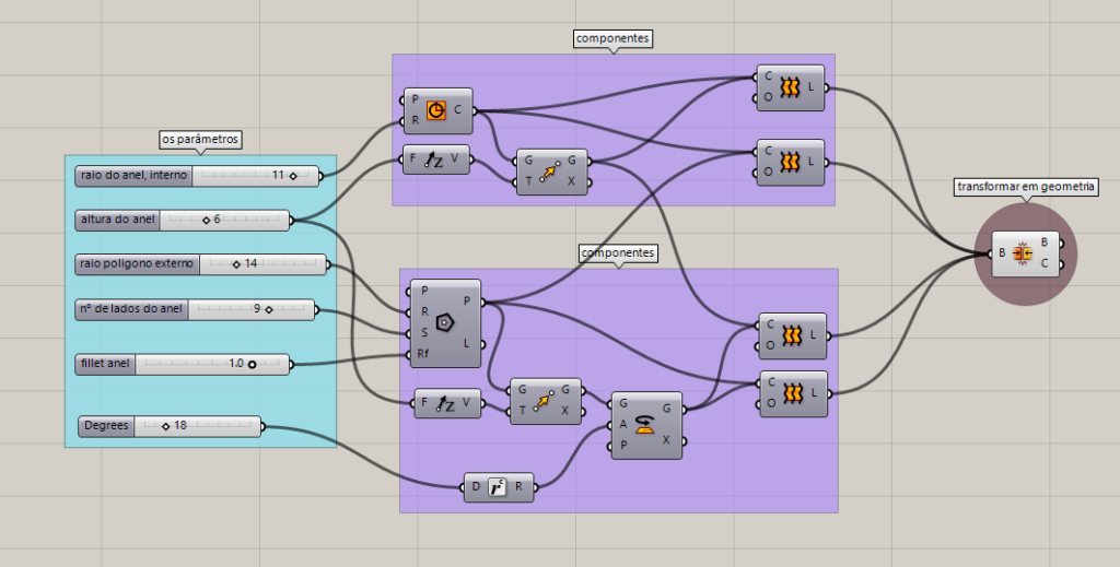
Grasshopper visual-programming definition showing parameter inputs, interconnected operations and generated geometric outputs
Parametric definitions organise geometry through connected inputs, operations and outputs, providing a structure that can be extended through panelisation, attribute management and iterative computation. Image: Orciuoli, CC BY-SA 4.0, via Wikimedia Commons.

Conclusion

The ten Grasshopper tools examined in this article demonstrate that computational design encompasses several distinct activities rather than a single method of generating complex forms.

Ladybug and Honeybee connect geometric design with environmental information and building-performance modelling.

Kangaroo2 and Karamba3D support different aspects of physical and structural exploration, from geometric relaxation to finite element analysis.

Wallacei provides a framework for investigating multi-objective optimisation, allowing designers to examine the trade-offs between competing performance criteria.

Pufferfish and Weaverbird extend geometric modelling through shape transformation, interpolation, subdivision and mesh operations.

LunchBox, eleFront and Anemone address the equally important challenges of panelisation, information management and iterative computation.

These capabilities can be combined into more sophisticated workflows.

For example, a computational designer could generate alternative building configurations, evaluate selected solar conditions, compare structural responses and explore the relationships among competing objectives.

However, connecting multiple plugins does not automatically produce a scientifically rigorous or architecturally appropriate result.

Each tool introduces its own assumptions, numerical methods, geometric representations and potential sources of error.

Environmental simulations require reliable climate data. Structural models require suitable material properties, load cases and support conditions. Optimisation depends on correctly formulated objectives, while geometric transformations require verification against fabrication and construction constraints.

A robust computational design workflow should therefore begin with a clearly defined question.

The designer should identify which variables can be controlled, which outputs need to be measured and which conditions must remain fixed.

The next step is to select the appropriate analytical or geometric tools rather than building an unnecessarily complex definition.

Installation and compatibility should also be managed deliberately.

McNeel recommends Rhino’s Package Manager as a primary route for discovering and managing supported plugins, while acknowledging that not every extension is available through it.

This matters because a Grasshopper definition may depend on specific component versions or external simulation engines.

Project teams should record the software versions and required dependencies, particularly when definitions need to be reopened or reviewed later.

Finally, computational outputs should remain interpretable.

A design team should be able to explain how a result was generated, what assumptions were used, which alternatives were considered and why a preferred proposal was selected.

The greatest value of Grasshopper plugins is not their ability to create visually complex architecture. It is their potential to make relationships between form, performance, information and design decisions explicit, testable and reproducible.

Computational tools become most useful when they extend professional judgment rather than obscure it behind increasingly complex algorithms.


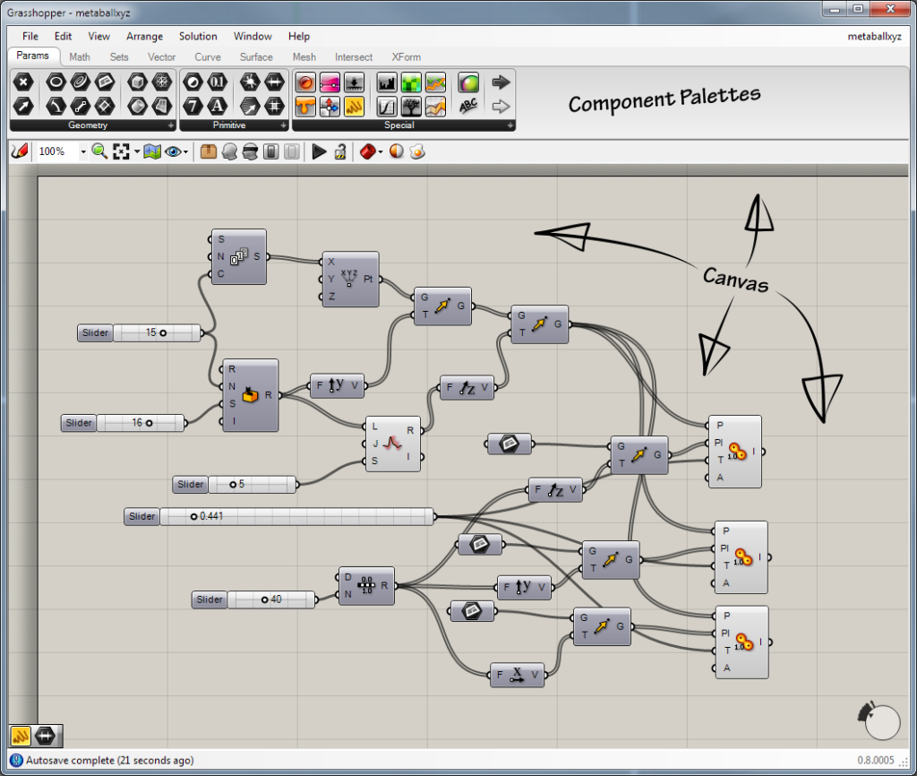
Grasshopper's visual-programming interface showing parameter sliders, interconnected components and the structure of an algorithmic definition
Grasshopper's visual-programming environment makes the relationships between design parameters and geometric operations visible, supporting more transparent computational workflows. Image: David Rutten, CC BY-SA 3.0, via Wikimedia Commons.
Leave a Reply

Your email address will not be published. Required fields are marked *

This site uses Akismet to reduce spam. Learn how your comment data is processed.

Related articles

UDL Thesis Publication 2025

Call for Abstracts now open!

Urban Mapping

MASTERCLASS

Urban Mapping, Analysis and Representation

Session Dates

21st- 22nd November 2026

Curating the best graduate thesis projects globally!

Publish your work and get recognized globally!

Free E-Book

From thesis to Portfolio

A Guide to Convert Academic Work into a Professional Portfolio”

Urban Design Lab

Be the part of our Network

  • Stay updated on workshops, design tools, and calls for collaboration

  • Thesis Report Writing for Architecture and Urban Studies

    Join Our WhatsApp Group

    Recent Posts

    Sign up for our Newsletter

    “Let’s explore the new avenues of Urban environment together “

    E-Book- From Thesis To Portfolio

    A Guide to Convert Academic Work into a Professional Portfolio